


PCB soldering defects: how to identify and prevent cold joints and dry joints
In any electronic assembly process, the quality of a solder joint has a direct impact on the reliability of the final product. A connection that initially appears correct can eventually become the source of intermittent failures, thermal issues, or premature breakdowns that are difficult to diagnose.
In sectors such as industrial electronics, automotive, telecommunications, or power devices, soldering defects are one of the main causes of PCB rework and rejection.
Problems such as cold joints and dry joints affect both the electrical conductivity and the mechanical strength of the connection, compromising long-term system stability.
Although these defects are often associated only with manual errors, the reality in industrial environments is usually far more complex. Thermal process stability, material quality, surface preparation, and compatibility between alloys and reflow profiles all have a direct impact on final solder quality.
Understanding how these defective joints are generated is essential to optimize production processes, reduce incidents, and improve electronic reliability.
Why soldering defects affect electronic reliability
A solder joint must not only ensure electrical continuity. It must also withstand vibrations, thermal cycles, humidity, and mechanical stress throughout the entire lifespan of the product.
When the bonding between the terminal and the pad is not properly achieved, the connection can progressively degrade. In many cases, the defect does not create an immediate failure, but rather small electrical variations or micro interruptions that appear after weeks or months of operation.
These types of issues are especially critical in industrial applications where:
- equipment operates continuously,
- significant temperature variations exist,
- or boards are exposed to constant vibration.
In automated SMT lines, even small deviations in wetting or temperature can generate recurring issues that are difficult to visually detect during the early production stages.
For this reason, preventing soldering defects has become a priority for both quality departments and SMT process engineers.
Difference between good solder joint, cold joint, and dry joint
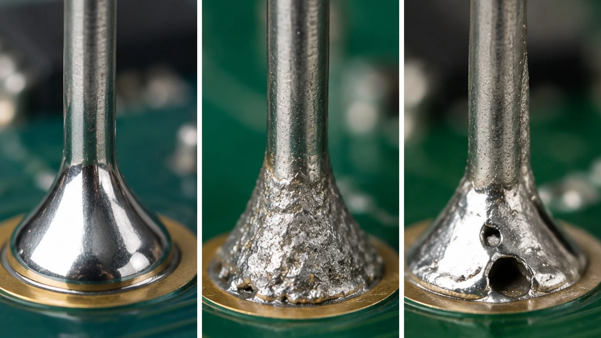
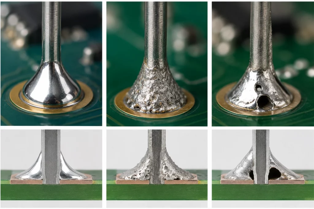
Although they may look visually similar, there are important differences between a correct solder joint, a cold joint, and a dry joint. The quality of wetting, thermal transfer, and metallurgical adhesion determines the final reliability of the connection.
Good solder joint
A proper solder joint presents a homogeneous, smooth surface evenly distributed over the pad and the component terminal. The solder flows correctly and creates uniform adhesion, ensuring both electrical conductivity and mechanical strength.
In automated industrial processes, this type of joint is the result of a proper balance between:
- temperature,
- exposure time,
- flux quality,
- and surface preparation.
Cold joint
A cold joint appears when the applied thermal energy is insufficient to create a stable metallurgical bond. Although it may look acceptable externally, internally it presents poor adhesion and incomplete wetting.
Visually, it is usually identified by:
- a dull or grainy appearance,
- irregular geometry,
- insufficient solder flow,
- or lack of surface uniformity.
In SMT environments, this defect is commonly related to:
- poorly adjusted thermal profiles,
- unstable heat transfer,
- or insufficient time during the reflow process.
Dry joint
A dry joint is more related to wetting issues than to insufficient temperature. The filler material fails to properly spread across the metallic surfaces, generating a partial and unstable connection.
Surface oxidation, contamination, or insufficient flux activation are usually determining factors.
In high-precision electronic processes, this type of defect may go visually unnoticed and only appear after prolonged thermal cycles or vibrations.
What causes a cold joint in PCB assembly
Cold joints are among the most frequent defects in electronic assembly, especially in production lines where thermal variations or frequent configuration changes occur.
Although the problem is often associated simply with a “lack of temperature,” multiple process-related factors are usually involved.
One of the most common causes is an insufficient thermal profile. If the solder does not reach the appropriate temperature or heating is not uniform, the solder will not flow correctly and the joint will lose both mechanical and electrical stability.
This issue is also frequently found in:
- components with high thermal mass,
- multilayer PCBs,
- or lead-free processes, where thermal requirements are higher.
Another important factor is exposure time. Even with the correct temperature, an excessively short contact time can prevent proper wetting and generate incomplete bonding.
Additionally, oxidized or contaminated surfaces considerably reduce adhesion quality. Residues, humidity, or oxidation on pads and terminals reduce the ability of the filler material to spread correctly.
Main causes of a cold joint
| Cause | Efecte en la unió |
| Insufficient temperature | Incomplete wetting |
| Short exposure time | Poor bonding |
| Multilayer PCB | Irregular thermal dissipation |
| Surface oxidation | Poor adhesion |
| Incorrect reflow profile | Unstable joint |
In automated SMT lines, cold joints also frequently appear after conveyor speed changes or incomplete recalibration of the reflow profile.
What causes a dry joint and how to detect it
Unlike cold joints, dry joints are directly related to wetting issues. The solder material fails to properly “wet” the metallic surface, causing partial and unstable adhesion.
In many cases, the origin lies in contaminated surfaces or advanced oxidation. Even small dirt particles or chemical residues can significantly alter flux behavior and reduce wetting capacity.
Flux selection also plays a critical role. Inadequate or insufficient flux makes oxide removal more difficult and directly affects solder flow during the process.
In industrial applications, this type of defect is commonly detected through:
- AOI inspection,
- visual analysis,
- functional testing,
- or microscopic inspection.
Typical indicators of a dry joint
| Indicator | What it usually indicates |
| Irregular coverage | Poor wetting |
| Incorrect meniscus | Insufficient flow |
| Visible separation | Partial adhesion |
| Localized accumulation | Unstable distribution |
How to reduce defects in SMT and THT processes
Reducing soldering defects requires a global process approach. In most cases, there is no single isolated cause, but rather a combination of thermal, chemical, and mechanical factors affecting joint stability.
Thermal profile control
One of the most critical aspects is thermal profile control. Each alloy and PCB type requires specific temperature and timing parameters to ensure correct wetting without generating excessive thermal stress.
In lead-free processes, this control becomes even more important due to higher working temperatures and smaller process margins.
Correct material selection
Material quality also directly affects process repeatability. Unstable alloys, low-quality flux, or materials with premature oxidation significantly increase defect risks.
Surface cleaning and preparation
Another key aspect is surface cleaning. Improper PCB or terminal preparation can completely compromise adhesion, even when the thermal profile is correct.
Inspection and quality control
Finally, inspection and quality control systems allow deviations to be detected before they generate major incidents. In advanced industrial environments, it is common to combine:
- AOI,
- X-ray inspection,
- statistical process control,
- and continuous thermal analysis.
Best practices to improve soldering quality
The stability and reliability of a solder joint depend on multiple variables. Maintaining a consistent process is essential to reduce defects and improve production repeatability.
Beyond temperature itself, small process details often make the difference between a stable production line and one with recurring incidents.
| Best practice | Benefit |
| Keep surfaces clean | Better wetting |
| Use the correct flux | Reduced oxidation |
| Review thermal profiles | Greater stability |
| Control storage conditions | Lower degradation |
| Avoid excessive solder | Fewer bridges and thermal stress |
In automated lines, small adjustments in speed or temperature can have a significant impact on final solder quality.